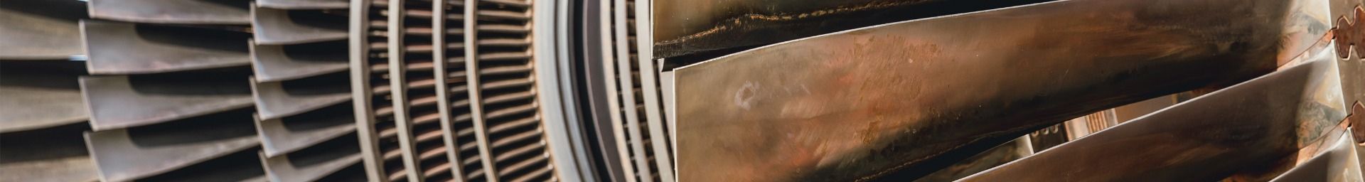

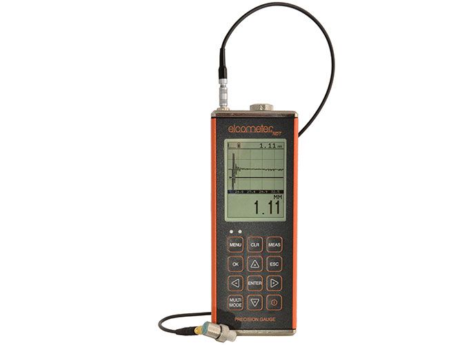
Elcometer PG70ABDL Ultrasonic Precision Thickness Gauge
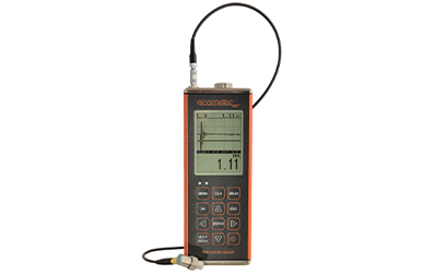
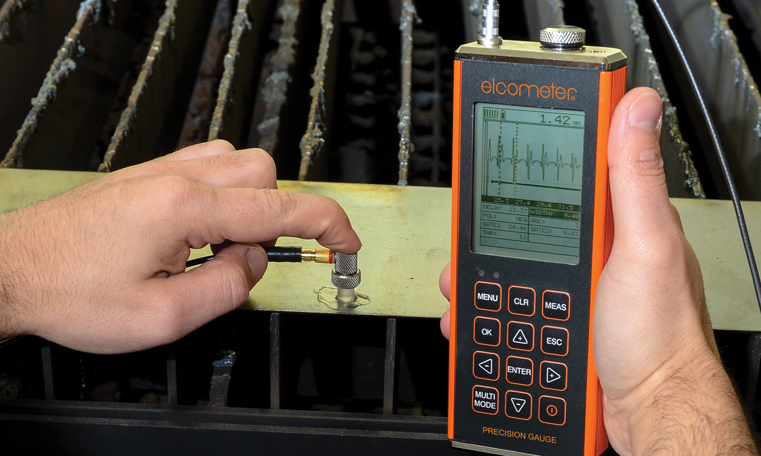
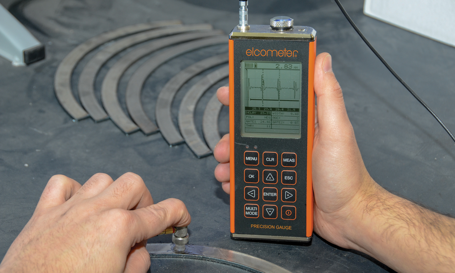
The PG70ABDL Precision Thickness Gauge can display the thickness value with A and B-Scan displays, allowing users to accurately assess a wide range of materials.
- Summary
-
Summary
-
Accuracy
Measures thin materials with pinpoint accuracy
Flexible & easy to use, the Elcometer PG70ABDL is able to measure the thinnest point of the substrate with maximum precision.
Powerful
Store each measurement for further analysis
Up to 4GB of readings and waveforms can be saved into the gauge memory as each measurement is taken, which can be downloaded later into an inspection application or into ElcoMaster® Software for further analysis and reporting.
Intelligent
User definable limits for pass/fail indication
Limits can be set on the Elcometer PG70ABDL for individual readings or for each batch with audible & visual alarms.
Customisable
Choose & customise the reading display
With a choice of display modes, the user can select the most appropriate option for their needs; Readings, Selected Statistics, Bar Graph, Run Chart & Differential Mode.
The Elcometer PG70ABDL offers user selectable resolution of either 0.01mm or 0.001mm (0.001/0.0001").
The auto find feature locates the detection point(s) and adjusts the display settings to bring the waveform into view.
The high speed scan feature on the PG70ABDL precision thickness gauge speeds up the inspection process by taking 250 measurements per second. Remove the transducer from the test material and display the minimum measurement scanned.
Features:
- 0.001mm high resolution
- Range of display options: A-Scan, B-Scan, Pulse-Echo, Echo-Echo
- Manual or AGC gain control with 110dB range, varies with mode selected
- Automatic gain control (AGC)
- User definable setups
- Multiple language display
- Visual and audible alarm with high and low limit settings for specific application tolerances.
- Multiple calibration and material selection options
- High speed scan: 250 readings per second
- Differential mode
- Minimal thickness alarm
- Data output and storage: 4GB internal memory
- Data management software
-
- Key Features
-
Key Features
Elcometer PG70ABDL Ultrasonic Precision Thickness Gauge
Features Explained
Repeatability / Stability Indicator
Consisting of 6 vertical bars, when all the bars are fully illuminated and the last digit on the digital thickness value is stable, the gauge is reliably measuring the material thickness.
High Speed Scan with Minimum Thickness Display
By significantly increasing the measurement refresh rate this mode allows the user to make scanned passes over the test material. The smallest thickness value is held in memory and displayed when scanning is complete. This feature can also be used in conjunction with the minimum & maximum limit alarm feature (model dependant).
Differential Mode
Once a user defined nominal thickness value has been set, the gauge will display the +/- thickness difference from the nominal value entered.
Limit Alarm Mode
The user can define minimum and maximum thickness limits. If the measurement falls outside the upper or lower limit a red LED will light and the beeper sounds. A green LED will light to indicate an acceptable thickness.
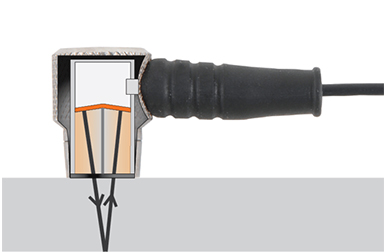
V-Path Correction
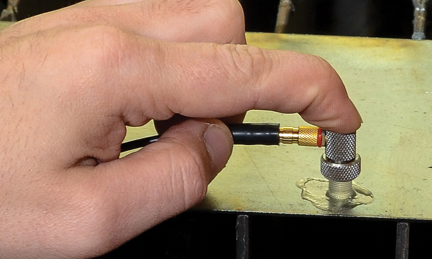
Dual element transducers consist of a probe with two crystals (one to transmit and one to receive the sound pulse). The crystals are separated by an acoustic barrier - generating a 'V-shaped' sound path as the sound travels from one element to the other. This path is slightly longer than the direct path therefore V-path correction is used to calculate the correct thickness.
Measurement Modes Explained
Pulse - Echo Mode (PE):
The normal display mode, measures the total thickness from the base of the transducer probe to the material density boundary (typically the back wall). Ideal for pit and flaw detection.Echo - Echo Mode (EE):
Also known as the ThruPaint™ Mode, EE ignores the coating thickness, displaying the material thickness from the top surface of the material to the material density boundary.Interface - Echo Mode (IE):
More accurate than the PE mode, IE displays the total thickness from the top surface to the material density boundary - i.e. ignores the couplant thickness.Display Modes Explained
Material Thickness Digits Display:
The standard display on all models, this displays the numerical thickness value in either millimetres (MM) or inches (IN).
Scan Bar Display:
A linear graphic display which allows users to graphically monitor changes in thickness readings. As the scale range can be adjusted by the user, this display is ideal for observing tiny variations in material thicknesses.
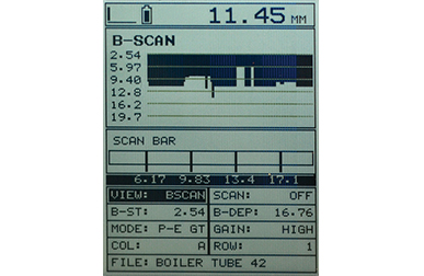
B-Scan Display:
A time based cross sectional 2D block view of the thickness provides a graphical view of the material thickness - ideal for relative depth analysis.
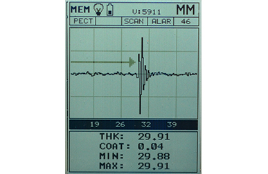
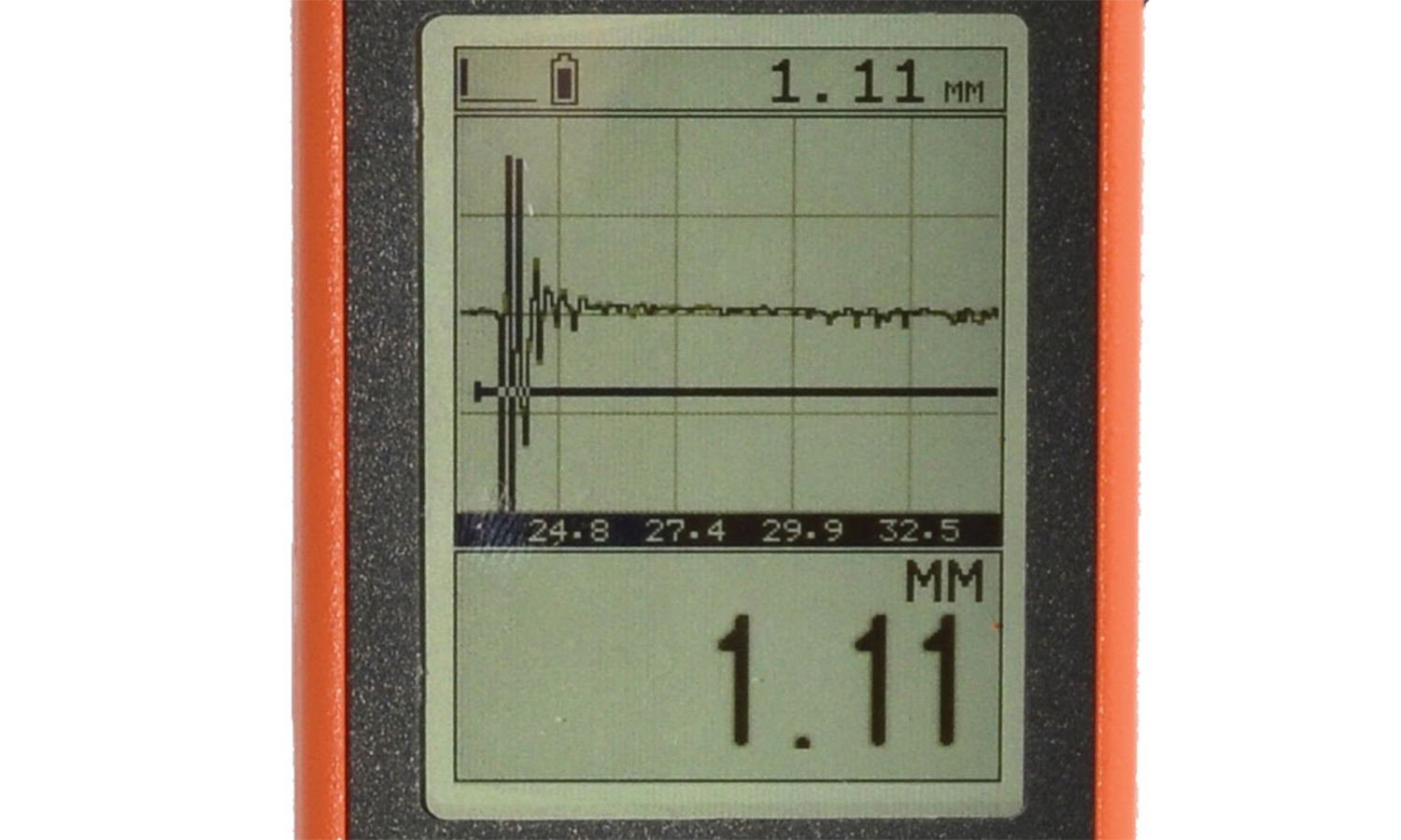
A-Scan Display; Full Wave (RF):
The A-Scan display shows the sine wave created by the reflected sound, or oscillation, from the material being measured. In RF mode the full wave form is displayed.
A-Scan Display; Rectified (+ or -):
Users can select to view either the positive or the negative cycle of the full waveform (RF). This rectified (RECT) display shows the amplitude of the echo versus the transit time.
-
- Product Features
-
Product FeaturesElcometer PG70ABDL Ultrasonic Precision Thickness Gauge
Model & Part Number PG70ABDL Display Mode Material thickness digits display B-Scan cross sectional display Combined B-Scan and digits display Scan bar display A-Scan display + Rectified, - Rectified, Full Waveform (RF) Measurement Mode PE, IE, EE, IEE, EEVMeasurement Rate Manual 8 readings per secondScan Mode 250 readings per secondScan bar display 10 to 33 readings per secondAdditional Features Additional Features Differential Mode Limit alarm mode Selectable resolution B-Scan display speed 10 to 200 readings per secondCalibration setups 64 custom user-definable setups, transferable to and from a PC archiveGates •3 adjustable gates, depending on measure mode selected
•Adjustable thresholdPulser Type Square wave pulser with adjustable pulse width (spike, thin, wide)
Adjustable 200 volt pulser: 100, 150 & 200 volts
Pulse repetition frequency up to 250HzGain Manual or Automatic Gain Control (AGC) with 110dB range, varies with mode selected
Time Dependent Gain (TDG), with variable start and slope
Adjustable damping (35, 50, 75, 300, 600 & 1500ohms)Timing Precision TCXO timing with single shot 100 MHz 8 bit ultra-low power digitizerMemory and Data Logging 4GB internal memory
Sequential and grid logging
Alpha numeric batch identification
OBSTRUCT indicates inaccessible locations
Bitmap graphic capture and capture viewerCalibration Options Single, two point, velocity and material typeTransducer Probe Type Single element with delay tip, pencil with delay tip and contact probesTransducer Frequency Range 1 - 25MHzTransducer Recognition manual - selectable from a listDisplay 1/8” VGA (greyscale), 62 x 45.7mm (2.4 x 1.8”) viewable areaDisplay Refresh Rate 25HzUnits (selectable) mm or inchesLED Backlight on / off / autoRepeatability / Stability Indicator Low Battery Indicator Battery Save Mode Auto Transducer Connector Type LEMO Interface USB
-
- Technical Information
-
Technical SpecificationElcometer PG70ABDL Ultrasonic Precision Thickness Gauge
Part Number Description Certificate PG70ABDL Ultrasonic Precision Thickness Gauge 
Transducer Probe Type Single element with delay tip, pencil with delay tip and contact probes Measurement Range1 Interface Echo (IE) on steel 1.27 - 25.4mm (0.050 - 1.0”) Interface Echo (IE) on plastic 0 - 0.127mm (0.005“) Echo Echo (contact) (EE) on steel 2.54 - 91.4mm (0.100 - 36”) Pulse Echo (contact) (PE) on steel 1 - 9,140mm (0.040 - 360”) Echo Echo Verified (EEV) on steel 2.54 - 152.4mm (0.100 - 6.0”) Interface Echo Echo (IEE) on steel 0.152 - 12.7mm (0.006 - 0.500”) Measurement Accuracy1 0.001mm (0.0001”) Resolution 0.01mm (0.001”), 0.001mm (0.0001”) selectable Velocity Calibration Range 309.88 - 18,542 m/s (0.0122 - 0.7300 in/μs) Memory 4GB internal memory Operating Temperature -10 to 60ºC (14 to 140ºF) Data Output USB Power Supply 3 x AA batteries and via USB Battery Life2 Alkaline–35 hrs
Nicad–10 hrs
NI-MH–35hrsGauge Weight 383g (13.5oz) - including batteries Gauge Dimensions 63.5 x 165 x 31.5mm (2.5 x 6.5 x 1.24”) Packing List Elcometer NDT PG70ABDL gauge, couplant, carry case, operating instructions, test certificate, 3 x AA batteries, ElcoMaster® software, transfer cable ●Test Certificate supplied as standard
1Measuring range & accuracy depends on material, surface conditions and the transducer selected
2Approximate battery life, when in continuous measurement mode.
-
- Standards
-
StandardsElcometer PG70ABDL Ultrasonic Precision Thickness Gauge
ASTM E 797, EN 14127, EN 15317
-
- Downloads
-
Downloads
-

Elcometer PG70ABDL Precision Thickness Gauge Instruction Manual
-

Elcometer PG70ABDL Precision Thickness Gauge Datasheet
-
PG70ABDL Precision Thickness Gauge Declaration of Conformity
- Part Numbers
-
Part NumbersElcometer PG70ABDL Ultrasonic Precision Thickness Gauge
-
 Elcometer PG70ABDL Ultrasonic Precision Thickness Gauge
- Part Number : PG70ABDL
- Accessories
-
AccessoriesElcometer PG70ABDL Ultrasonic Precision Thickness Gauge
 Part Number: TC-24034-1
-
Part Number: TC-24034-2
-
Part Number: TC-24034-3
-
Part Number: TC-24034-9
-
Part Number: TL-24030-1
-
Part Number: TL-24030-2
-
Part Number: TL-24030-3
-
Part Number: TL-24031
-
Part Number: TL-24032
-
Part Number: TD-24033-1
-
Part Number: TD-24033-2
-
Part Number: TD-24033-3
-
Part Number: TD-24033-4
-
Part Number: TD-24033-5
-
Part Number: TD-24033-6
-
Part Number: TD-24033-7
-
Part Number: TD-24033-8
-
Part Number: TZ-24035
-
Elcometer PG70ABDL Ultrasonic Precision Thickness Gauge
The PG70ABDL Precision Thickness Gauge can display the thickness value with A and B-Scan displays, allowing users to accurately assess a wide range of materials.
Accuracy
Measures thin materials with pinpoint accuracy
Flexible & easy to use, the Elcometer PG70ABDL is able to measure the thinnest point of the substrate with maximum precision.
Powerful
Store each measurement for further analysis
Up to 4GB of readings and waveforms can be saved into the gauge memory as each measurement is taken, which can be downloaded later into an inspection application or into ElcoMaster® Software for further analysis and reporting.
Intelligent
User definable limits for pass/fail indication
Limits can be set on the Elcometer PG70ABDL for individual readings or for each batch with audible & visual alarms.
Customisable
Choose & customise the reading display
With a choice of display modes, the user can select the most appropriate option for their needs; Readings, Selected Statistics, Bar Graph, Run Chart & Differential Mode.
Summary
Elcometer PG70ABDL Ultrasonic Precision Thickness Gauge
The Elcometer PG70ABDL offers user selectable resolution of either 0.01mm or 0.001mm (0.001/0.0001").
The auto find feature locates the detection point(s) and adjusts the display settings to bring the waveform into view.
The high speed scan feature on the PG70ABDL precision thickness gauge speeds up the inspection process by taking 250 measurements per second. Remove the transducer from the test material and display the minimum measurement scanned.
Features:
- 0.001mm high resolution
- Range of display options: A-Scan, B-Scan, Pulse-Echo, Echo-Echo
- Manual or AGC gain control with 110dB range, varies with mode selected
- Automatic gain control (AGC)
- User definable setups
- Multiple language display
- Visual and audible alarm with high and low limit settings for specific application tolerances.
- Multiple calibration and material selection options
- High speed scan: 250 readings per second
- Differential mode
- Minimal thickness alarm
- Data output and storage: 4GB internal memory
- Data management software
Downloads-
Elcometer PG70ABDL Precision Thickness Gauge Instruction Manual
-
Elcometer PG70ABDL Precision Thickness Gauge Datasheet
-
PG70ABDL Precision Thickness Gauge Declaration of Conformity
Key Features
Elcometer PG70ABDL Ultrasonic Precision Thickness Gauge
Features Explained
Repeatability / Stability Indicator
Consisting of 6 vertical bars, when all the bars are fully illuminated and the last digit on the digital thickness value is stable, the gauge is reliably measuring the material thickness.
High Speed Scan with Minimum Thickness Display
By significantly increasing the measurement refresh rate this mode allows the user to make scanned passes over the test material. The smallest thickness value is held in memory and displayed when scanning is complete. This feature can also be used in conjunction with the minimum & maximum limit alarm feature (model dependant).
Differential Mode
Once a user defined nominal thickness value has been set, the gauge will display the +/- thickness difference from the nominal value entered.
Limit Alarm Mode
The user can define minimum and maximum thickness limits. If the measurement falls outside the upper or lower limit a red LED will light and the beeper sounds. A green LED will light to indicate an acceptable thickness.
V-Path Correction
Dual element transducers consist of a probe with two crystals (one to transmit and one to receive the sound pulse). The crystals are separated by an acoustic barrier - generating a 'V-shaped' sound path as the sound travels from one element to the other. This path is slightly longer than the direct path therefore V-path correction is used to calculate the correct thickness.
Measurement Modes Explained
Pulse - Echo Mode (PE):
The normal display mode, measures the total thickness from the base of the transducer probe to the material density boundary (typically the back wall). Ideal for pit and flaw detection.Echo - Echo Mode (EE):
Also known as the ThruPaint™ Mode, EE ignores the coating thickness, displaying the material thickness from the top surface of the material to the material density boundary.Interface - Echo Mode (IE):
More accurate than the PE mode, IE displays the total thickness from the top surface to the material density boundary - i.e. ignores the couplant thickness.Display Modes Explained
Material Thickness Digits Display:
The standard display on all models, this displays the numerical thickness value in either millimetres (MM) or inches (IN).
Scan Bar Display:
A linear graphic display which allows users to graphically monitor changes in thickness readings. As the scale range can be adjusted by the user, this display is ideal for observing tiny variations in material thicknesses.
B-Scan Display:
A time based cross sectional 2D block view of the thickness provides a graphical view of the material thickness - ideal for relative depth analysis.
A-Scan Display; Full Wave (RF):
The A-Scan display shows the sine wave created by the reflected sound, or oscillation, from the material being measured. In RF mode the full wave form is displayed.
A-Scan Display; Rectified (+ or -):
Users can select to view either the positive or the negative cycle of the full waveform (RF). This rectified (RECT) display shows the amplitude of the echo versus the transit time.
Product FeaturesElcometer PG70ABDL Ultrasonic Precision Thickness GaugeModel & Part Number PG70ABDL Display Mode Material thickness digits display B-Scan cross sectional display Combined B-Scan and digits display Scan bar display A-Scan display + Rectified, - Rectified, Full Waveform (RF) Measurement Mode PE, IE, EE, IEE, EEVMeasurement Rate Manual 8 readings per secondScan Mode 250 readings per secondScan bar display 10 to 33 readings per secondAdditional Features Additional Features Differential Mode Limit alarm mode Selectable resolution B-Scan display speed 10 to 200 readings per secondCalibration setups 64 custom user-definable setups, transferable to and from a PC archiveGates •3 adjustable gates, depending on measure mode selected
•Adjustable thresholdPulser Type Square wave pulser with adjustable pulse width (spike, thin, wide)
Adjustable 200 volt pulser: 100, 150 & 200 volts
Pulse repetition frequency up to 250HzGain Manual or Automatic Gain Control (AGC) with 110dB range, varies with mode selected
Time Dependent Gain (TDG), with variable start and slope
Adjustable damping (35, 50, 75, 300, 600 & 1500ohms)Timing Precision TCXO timing with single shot 100 MHz 8 bit ultra-low power digitizerMemory and Data Logging 4GB internal memory
Sequential and grid logging
Alpha numeric batch identification
OBSTRUCT indicates inaccessible locations
Bitmap graphic capture and capture viewerCalibration Options Single, two point, velocity and material typeTransducer Probe Type Single element with delay tip, pencil with delay tip and contact probesTransducer Frequency Range 1 - 25MHzTransducer Recognition manual - selectable from a listDisplay 1/8” VGA (greyscale), 62 x 45.7mm (2.4 x 1.8”) viewable areaDisplay Refresh Rate 25HzUnits (selectable) mm or inchesLED Backlight on / off / autoRepeatability / Stability Indicator Low Battery Indicator Battery Save Mode Auto Transducer Connector Type LEMO Interface USB Technical SpecificationElcometer PG70ABDL Ultrasonic Precision Thickness GaugePart Number Description Certificate PG70ABDL Ultrasonic Precision Thickness Gauge Transducer Probe Type Single element with delay tip, pencil with delay tip and contact probes Measurement Range1 Interface Echo (IE) on steel 1.27 - 25.4mm (0.050 - 1.0”) Interface Echo (IE) on plastic 0 - 0.127mm (0.005“) Echo Echo (contact) (EE) on steel 2.54 - 91.4mm (0.100 - 36”) Pulse Echo (contact) (PE) on steel 1 - 9,140mm (0.040 - 360”) Echo Echo Verified (EEV) on steel 2.54 - 152.4mm (0.100 - 6.0”) Interface Echo Echo (IEE) on steel 0.152 - 12.7mm (0.006 - 0.500”) Measurement Accuracy1 0.001mm (0.0001”) Resolution 0.01mm (0.001”), 0.001mm (0.0001”) selectable Velocity Calibration Range 309.88 - 18,542 m/s (0.0122 - 0.7300 in/μs) Memory 4GB internal memory Operating Temperature -10 to 60ºC (14 to 140ºF) Data Output USB Power Supply 3 x AA batteries and via USB Battery Life2 Alkaline–35 hrs
Nicad–10 hrs
NI-MH–35hrsGauge Weight 383g (13.5oz) - including batteries Gauge Dimensions 63.5 x 165 x 31.5mm (2.5 x 6.5 x 1.24”) Packing List Elcometer NDT PG70ABDL gauge, couplant, carry case, operating instructions, test certificate, 3 x AA batteries, ElcoMaster® software, transfer cable ●Test Certificate supplied as standard
1Measuring range & accuracy depends on material, surface conditions and the transducer selected
2Approximate battery life, when in continuous measurement mode.Part NumbersElcometer PG70ABDL Ultrasonic Precision Thickness Gauge-
Elcometer PG70ABDL Ultrasonic Precision Thickness Gauge
- Part Number : PG70ABDL
AccessoriesElcometer PG70ABDL Ultrasonic Precision Thickness Gauge-
Part Number: TC-24034-1
-
Part Number: TC-24034-2
-
Part Number: TC-24034-3
-
Part Number: TC-24034-9
-
Part Number: TL-24030-1
-
Part Number: TL-24030-2
-
Part Number: TL-24030-3
-
Part Number: TL-24031
-
Part Number: TL-24032
-
Part Number: TD-24033-1
-
Part Number: TD-24033-2
-
Part Number: TD-24033-3
-
Part Number: TD-24033-4
-
Part Number: TD-24033-5
-
Part Number: TD-24033-6
-
Part Number: TD-24033-7
-
Part Number: TD-24033-8
-
Part Number: TZ-24035
-
-